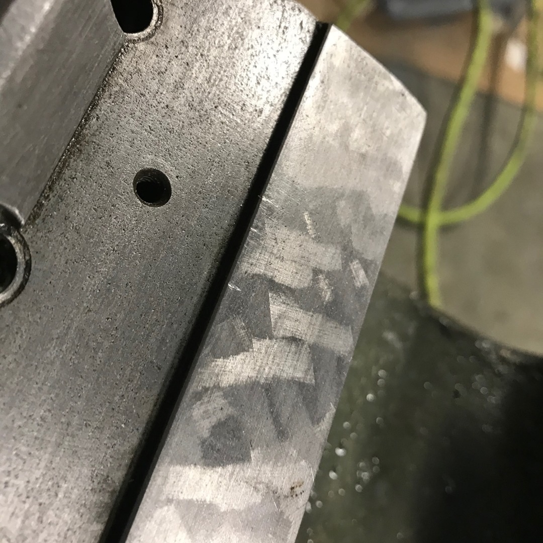
You can still see some of the original scraping on the ways that were hidden by the headstock of my 80 year old lathe. The exposed, working area, of the ways have been worn down quite a bit. I thought about having them ground and then hand scraping them, but I’m not sure it would be worth it.
.
.
.
.
.
.
.
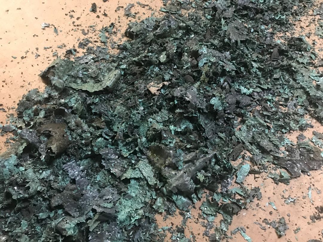
I have no idea how many layers of paint this is.
I have no idea how many layers of paint this is. But I am glad it’s no longer part of my lathe.
.
.
.
.
.
.
.
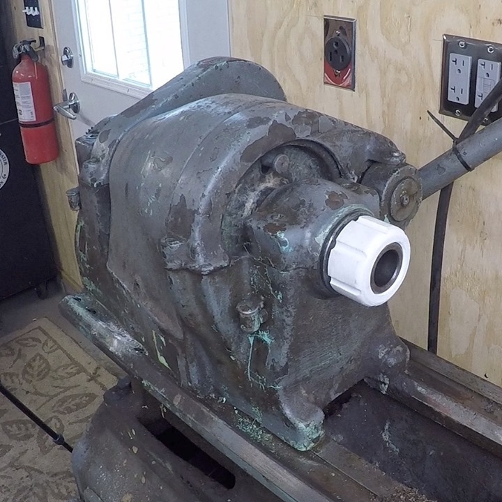
Continuing work on this 1941 South Bend Lathe.
Continuing work on this 1941 South Bend Lathe. Spent some time taking apart the headstock. The white thing in the photo is a 3D printed thread protector. Not completely necessary, but I wanted to try making it. The headstock houses the drive pulleys as well as a back gear that slows the rotational speed of the spindle, as well as the spindle itself.
.
.
.
.
.
.
.
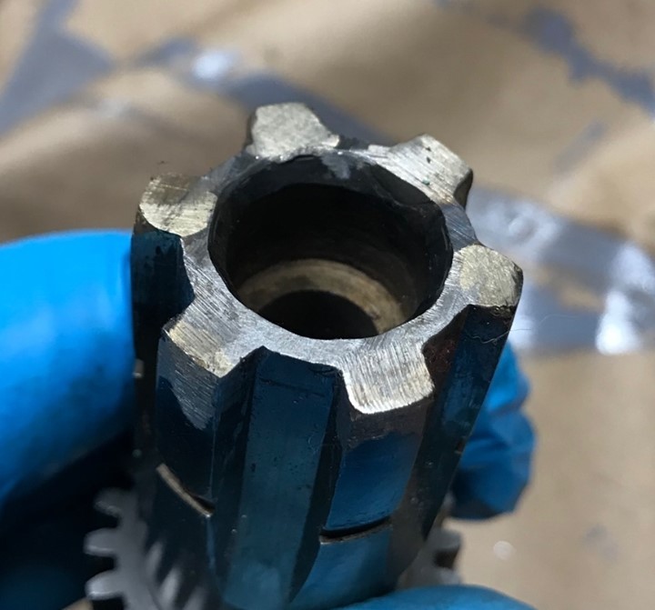
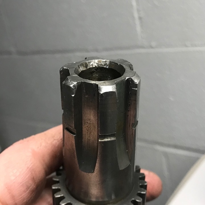
I used some @bluedemonweld Aluminum Bronze TIG rod to repair the worn splines on this shaft
I used some @bluedemonweld Aluminum Bronze TIG rod to repair the worn splines on this shaft from the power feed clutch on an 80 year old lathe. I have never done something like this before, and I think it went well and came out OK. Check the link my bio for a video.
•
•
•
•
•
This is a splined shaft that is part of the power feed clutch on the 1941 South Bend lathe.
This is a splined shaft that is part of the power feed clutch on the 1941 South Bend lathe I am restoring. The splines have been rounded over at the top after 80 years of use. I’m thinking I might TIG braze some aluminum bronze on them and hand file them to shape. I’ve had good luck using it on cast steel, it should work here.
.
.
.
.
.
.
.
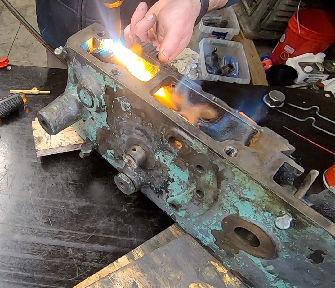
Fire! I needed some heat to disassemble parts of the apron of my 1941 South Bend lathe.
Fire! I needed some heat to disassemble parts of the apron of my 1941 South Bend lathe. There were a number of taper pins that wouldn’t budge, no matter how hard I hit them. I used some heat to try and expand the material around the pin, making it a little easier to get. Worked most of the time.
.
.
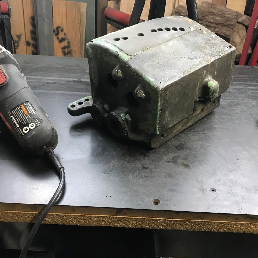
Now that the quick change gearbox is out and disassembled.
Now that the quick change gearbox is out and disassembled, I can spend some time cleaning up the paint and remainder of the grease. I’m going to repaint this with some @rustoleum oil based enamel
.
.
.
.
.
.
.
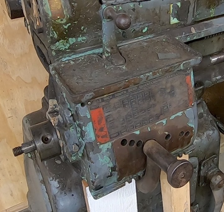
Spent some time removing and disassembling the single tumbler quick change gear box
Spent some time removing and disassembling the single tumbler quick change gear box from my 1941 13″ South Bend lathe. The gear box allows you to accurately set the rotation of the lead screw in relationship to the speed of the spindle. This makes it a snap to cut threads as well as set the feed rate for turning and facing operations.
.
.
.
.
.
.
.
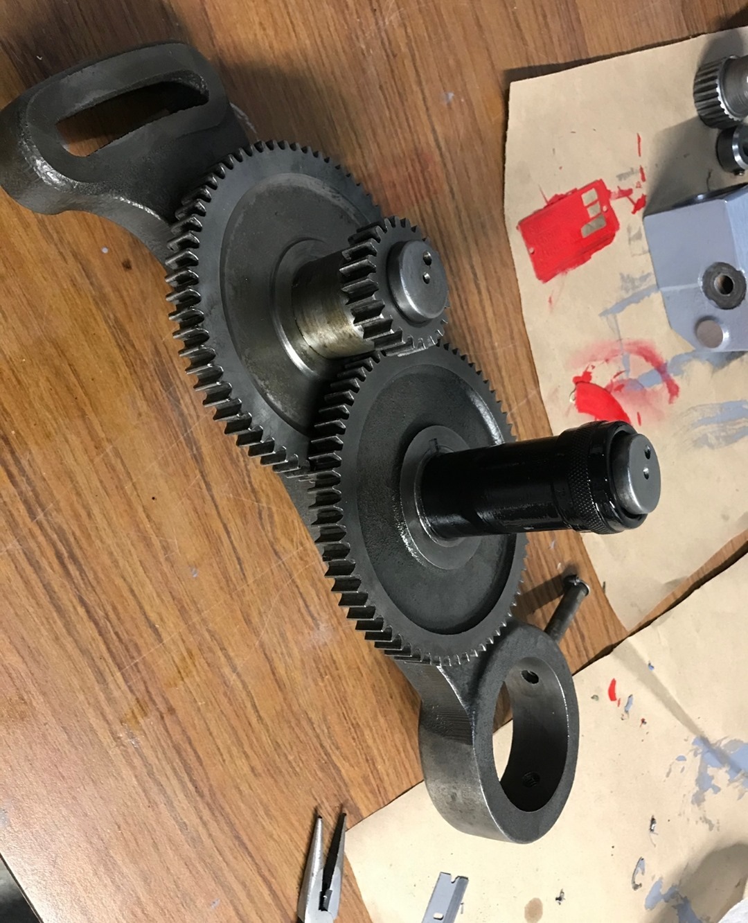
Not sure what I want to do about these gears.
Not sure what I want to do about these gears. I’d really like to get the shafts out. I may try a gear puller and see if that won’t work them loose. But then I’d still have to get them back in once I clean them up.
.
.
.
.
.
.
.
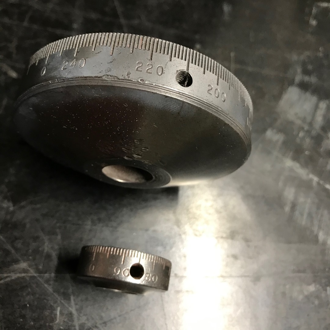
The top dial is for the cross slide on my 1941 South Bend lathe.
The top dial is for the cross slide on my 1941 South Bend lathe. The bottom one is for the compound. If you look close, you can see they are different scales. The cross slide feed screw was changed from the factory 10 threads per inch with an indirect reading dial, to an 8 thread per inch screw with an direct reading dial. For the cross slide, the direct reading dial is a little easier to work with. For every turn of the handle, the tool moves in 0.125 inches, but would REMOVE 0.250 inches off the diameter. You would rarely, if ever, measure the RADIUS of the part you are turning, so this configuration makes the math much easier.
.
.
.
.
.
.
.

